
Centrifugal Pump maintenance may be described as a routine operation carried out to keep a machine, equipment, or item in the best possible condition so that the work can be completed with the least amount of money spent. In contrast, maintenance engineering is a multidisciplinary area in which the use of engineering concepts for improved performance, availability, and equipment health optimizes cost, equipment condition, and health. Maintenance engineers must have interpersonal, communication, and managerial skills and an understanding of probability, logistics, and equipment operation concepts. Maintenance engineering necessitates applying technical principles and expertise to improve performance while keeping costs and time to a minimum.
INTRODUCTION
A pump is a machine/device that is used for displacing fluid from one level of the head to another. They are used for a wide range of applications such as displacing different types of products like water, chemicals, petroleum, wastewater, oil, sludge, slurry, food, etc. The basic mechanism of the pump is “It delivers the flow by converting the energy of a prime mover first into velocity or kinetic energy and then into pressure energy of the fluid that is being pumped.
The energy changes occur by two main parts of the pump i.e., the impeller and the diffuser.” The impeller is a rotating part that converts driver energy into kinetic energy and the diffuse is a stationary part that converts kinetic energy into pressure energy. Despite different varieties of pumps, the working principle is basically similar. Pumps are of two types.
- Positive displacement pumps
- Rotodynamic pump
Positive displacement pumps move fixed volumes of fluid repeatedly and move through the system mechanically. The pumping action is cyclic and can be driven by pistons, screws, gears, etc.
Centrifugal Pump
Centrifugal pump is a type of rotodynamic pump that is used to transport fluids by the conversion of rotational kinetic energy into hydrodynamic energy of the fluid flow. The required rotational energy comes from an engine or an electric motor. It is one of the simplest equipment of any production system. The impeller rotates rapidly along its axis where fluid gets entered and is cast out by means of centrifugal force along its perimeter/circumference through the impeller’s vane tips.
This action increases the velocity of fluids as well as pressure and directs it toward the pump outlet. The casing of the pump is designed to constrict the fluid flow from the inlet, direct it to the impeller, reduce the velocity of fluid, and control the fluid before discharge. They are classified as axial, radial, and mixed according to their behavior and how they direct the fluid flow.
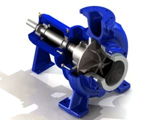
Table 1: Types, applications, and features of centrifugal pump
| Type | Application | Features |
| Canned motor pump | Hydrocarbons, chemicals where any leakage is not permitted | Impeller directly attached to the motor rotor; wetted parts contained in can |
| Magnetic drive pump | Impeller driven by closed coupled magnets | |
| Chopper/grinder pump | Wastewater in industrial, chemical, and food processing/sewage | Impeller fitted with grinding teeth chop solids |
| Circulator pump | Heating, ventilation, and air conditioning | Inline compact design |
| Multistage pump | High-pressure applications | Multiple impellers for increased discharge pressures |
| Cryogenic pump | Liquid natural gas, coolants | Special construction materials to tolerate low temperatures |
| Trash pump | Draining mines, pits, construction sites | Designed to pump water containing solid debris |
| Slurry pump | Mining, mineral processing, industrial slurries | Designed to handle and withstand highly abrasive slurries |
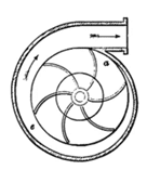
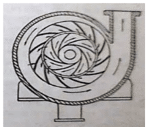
Working mechanism
A centrifugal pump is a mechanical device designed to move fluid by means of the transfer of rotational energy from one or more driven rotors called impellers. The impeller is the key component of a centrifugal pump. Impeller is made by the series of curved vanes which is then sandwiched between two disc. Fluid enters the impeller at its axis called the eye and exits along the circumference of those vanes. The impeller is connected through the drive shaft to a motor which rotates at high speed.
The rotational motion of the impeller accelerates the fluid out through the impeller vanes into the pump casing. Pump casings are of two types: volute & diffuser. The purpose of these types is to discharge the fluid at controlled pressure.
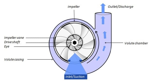
As the electric motors start rotating, the impeller also gets started which creates suction on the suction pipe. Due to the suction effect, fluid enters from the inlet into the casing through the eye of an impeller. The centrifugal force acting on the fluid due to rotation makes the fluid rotate outward along the circumference. The area of the casing increases slowly in the direction of rotation, as velocity decreases, pressure is maximized by which fluid goes to the required location.
Components
The basic components of a centrifugal pump are:
Impeller
It is a wheel or rotor that has a succession of rearward curled blades or vanes. It is positioned on a shaft that is connected to an external source of energy, which transfers liquid energy to the impeller, causing it to spin.
There are three types of impellers. They are:
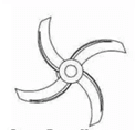
- Open impeller
Smaller pumps with open impellers are easier to clean and repair. It has vanes that are attached to the central hub and are directly placed onto a shaft; there is no wall that may surround the vanes, making open impellers weaker than other impellers.
- Semi-closed impeller
Semi-closed impellers are used for transporting fluid which have a back wall that adds strength to the impeller, but the other side is exposed to the interior of the pump housing. The efficiency of this semi-closed impeller is less compared to the closed impeller.
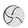
- Closed impeller
The closed impeller has a front and back wall around the vanes which can add extra strength compared to semi-closed impellers. The closed impellers are generally used in larger pumps where high-speed conditions are present.

Casing
It is a pipe that connects the top end of the pump’s intake to the center of the impeller, also known as the eye. The double-end response pump is made up of two suction pipes that are linked to the eye on both sides. To lift, the lower end sinks into liquid. The bottom end is connected to a foot valve and a strainer.
There are three types of casing used in a centrifugal pump. They are:
- Volute Casing
The cross-sectional area increases towards the outlet of the pump. The design causes the fluid pressure to increase toward the outlet of the pump.
- Vortex Casing
It is much more efficient than volute casing and a circular chamber is provided between the casing and impeller in the case.
- Diffuser Casing
It increases the efficiency by gradual expansion and less turbulent area for the liquid to flow in the pump.
Delivery Pipe
It is a pipe that is linked at its lower end to the pump’s outlet and transports the liquid to the desired height. A valve is supplied at the pump’s exit on the delivery pipe to control the flow from the pump into the delivery pipe.
Suction pope with foot valve and strainer
The suction pipe is attached to the impeller’s intake, while the other end is plunged into the sump of water. It has a foot valve and a strainer at the water end. The foot valve is a one-way valve that only opens vertically. The strainer is used to filter out undesirable particles in the water, preventing the centrifugal pump from being clogged.
Driveshaft
The driveshaft is fixed at the center of the pump, and it rotates in the same direction as the runner, and electricity is generated from the driveshaft.
Performance parameter of centrifugal pump
The key performance parameters of centrifugal pumps are:
- Capacity
- Head
- BHP (Brake horsepower)
- BEP (Best efficiency point)
- Specific speed
Capacity
Capacity means the flow rate with which the liquid is transferred/pushed by the pump up to the desired place. It is measured in cubic meters per hour or gallons per minute. It changes with a change in the operation of the process. The capacity depends on the factors like:
- Liquid characteristics (density, viscosity)
- Size of pipe, inlet, and outlet
- Impeller size and rotational speed
- Sizes and shapes of cavities between the vanes
- Pump suction and discharge temperature and pressure conditions
The relationship is given by:
Q= 449*V*A
- Where, Q= capacity
- V= velocity of flow
- An area of pipe
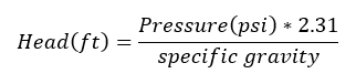
Head
The pressure at any point in a vertical column of liquid can be caused by its weight. The height of this column is called the static head and is expressed in feet of liquid. In other words, the head is a measurement of the height of the liquid column that the pump could create from the kinetic energy imparted from the liquid. The static head corresponding to any specific pressure is dependent upon the weight of the liquid according to the following formula.
Brake Horsepower
The work performed by a pump is a function of the total head and the weight of the liquid pumped each time. Pump input or brake horsepower (BHP) is the actual horsepower delivered to the pump shaft. Pump output or hydraulic or water horsepower (WHP) is the liquid horsepower delivered by the pump. These two terms are defined by the following formulas.
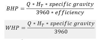
Where, Q= capacity in gallons per minute
HT= Total differential head, ft
Best efficiency point (BEP)
The capacity at maximum impeller diameter has the best efficiency. It determines the most efficient energy conversion. The pump efficiency at design should be considered while sizing and selecting centrifugal pumps for a specific application.
MAINTENANCE OVERVIEW
Pumps are frequently made to function at a single location called the Best Efficiency Point (BEP). A pump’s performance degrades when its parts start to wear out. Operating outside this range can cause problems, including cavitation, vibration, increased bearing or seal wear, and excessive temperature rise. If performance problems are resolved later, diminishing performance frequently begins gradually before escalating swiftly till failure. Pump maintenance is necessary to guarantee that process performance is returned to the standards set out in the original design and to restore performance and dependability. Maintenance is a technical and administrative effort that first focuses on system restoration.
Confirming correct operation, preserving system life, assuring safety, and ensuring human well-being are the significant goals of maintenance. The method of maintenance aids in maximizing the system’s efficiency. Maintenance plays a significant role in mechanical engineering.
Different types of maintenance are followed for centrifugal pumps.
Corrective Maintenance
When a failure occurs, corrective maintenance is undertaken. The unit may be leaky, less efficient, or have a stopped pump or tripped motor, which would cause a loss of output and necessitate immediate parts sourcing and installation. Sometimes both specialized lifting equipment and specialized labor may be needed. Downtime costs £12K on average for each event, takes 8 hours to address, and happens four times a year. Without considering consumer displeasure and product waste, thus it is best to prevent this circumstance.
Preventive Maintenance
Inspection and repair are planned as part of preventative maintenance at regular intervals (daily, weekly, monthly, or annually) or based on the number of operating hours. By disassembling the unit, visual examinations are performed both internally and externally. Gaskets and mechanical seals are replaced, and the pump parts’ wear is examined.
Predictive maintenance
The ideal situation is to make sure that parts are changed before failure, but not too early that they have had minimal wear and valuable time is spent evaluating parts that are otherwise in good condition. This may be done by using a monitoring device; with the correct data obtained, pump failure can be predicted with an accuracy of 80–95% between three and twelve months in advance. With DN100 pumps having an average lead time of three months or more and units older than five years, it is critical that spare parts be either on hand or ordered in advance if failure is expected.
Condition-based maintenance
The CBM approach constantly examines the centrifugal pump’s operational state, which aids in identifying any anomalies. This method provides prompt upkeep and precise decision-making, which unquestionably decreases downtime and boosts the availability of the pump in the working area.
Reliability centered maintenance (RCM)
It is useful when the system’s behavior cannot be predicted precisely based on prior observations and domain information. RCM enables us to develop a maintenance plan that addresses the root cause of the failure while also providing a methodical technique for defining the routine maintenance schedule. This maintenance approach uses statistical techniques such as Failure Mode Effect Analysis (FMEA), Fault Tree Analysis (FTA), and Failure Mode Effect Critical Analysis (FMECA) to extract information that aids in the identification of the failure cause. Its benefits include less wasteful, premature, and unplanned maintenance.
Risk-Based Maintenance
The amount of risk of failure in the system is assessed first in this technique. Following that, the risk is assessed, and maintenance work is performed.
Total productive maintenance
Most industrial and production industries employ this strategy to extend the usable life of pump components and gain a competitive edge in the global market in terms of cost and quality. TPM has difficulties such as poor management of production associates, a lack of continuous momentum, and a lack of resources.
Software based Maintenance
The software program has drastically altered production processes and system maintenance, including scheduling, planning, documenting, prediction, maintainability, regulating, and decision-making. FRANTIC, PERDEC, REGINA, RELCODE, and other software packages are available for maintenance optimization. CMMS, or Computerized Maintenance Management System, is another effective technology utilized for maintenance management in many businesses. The data collection agents are assigned to several critical sections. These data-gathering bots are launched to perform monitoring tasks. The collected/collected data is summarized, and the findings are compared to the Weibull distribution. As a result, CMMS allows and encourages maintenance engineers to forecast system dependability, failure probability, and remaining life in the future.
Failure detection techniques
Differential pressure analysis, temperature analysis, ultrasonic systems, oil analysis, vibration analysis, acoustic emissions, and other technologies are commonly used for system diagnosis. Some of the most popular monitoring techniques include vibration analysis, acoustic emission analysis, frequency analysis, pressure analysis, flow rate analysis, and temperature analysis.
- Differential pressure: Calculate the difference between the intake and exit pressures of the pump to ensure it is running on a curve.
- Vibration: Vibration analysis has been utilized in defect diagnosis by monitoring and evaluating machine vibration. This approach aids in determining the type and severity of the problem and hence in predicting the usable life of the equipment. The vibration signals are typically obtained using an accelerometer installed on the exterior surface of the bearing housing. These signals are made up of vibrations from the centrifugal pump’s bearing, shaft, and other components, and they are recorded at various frequencies. The severity of the vibration may be determined by comparing it to the historical baseline value. Analysts can identify the problem and its leading cause by examining the frequencies.
- Excess temperature: Check the temperature of the motor, bearings, and casing. Thermal imaging cameras can rapidly detect excessive heat without needing a halt, disassembling, or interaction with the equipment.
MAINTENANCE PROGRAM
Maintenance of centrifugal pump maintenance programs are classified into three types: routine, quarterly, and yearly. Routine maintenance is the process of scheduling inspections, logging, and repairs. This focuses on components that are early warning signs of possible failure.
Routine Maintenance
Bearing and lubricant condition
Keep track of and monitor bearing temperatures, lubrication levels, and vibration. The lubricant should be clear and free of bubbles. If bubbling occurs, it is a good indicator that extra lubrication is needed to reduce the temperature of the bearings. An increase in vibration in the bearings may indicate impending bearing failure.
Shaft seal condition
- Examine the mechanical seals. There should be no apparent symptoms of leaking.
- Inspect the pump’s packing during downtime to ensure appropriate lubrication. If the packing appears crushed and dry, replace it and apply oil according to the operating instructions.
Pump discharge pressure
The total produced head pressure of the pump is determined by the pressure differential between the suction and discharge gauges. Confirm that this value is within the pump’s specified range. This can be found on the manufacturer’s website or in operating instructions.
Overall Pump Vibration
Monitoring total pump vibration helps indicate probable pump failure. Changes in pump alignment, bearing failures, cavitation, and clogs in the suction and discharge lines can all cause excessive vibration.
Quarterly maintenance
- Check the pump’s base for stability and the tightness of the hold-down bolts.
- As a rule of thumb, for oil-lubricated pumps, change the oil after the first 200 hours of operation for a new pump. Then every three months or after 2,000 operational hours, whichever comes first. Oil change intervals and oil grade will be specified in the operation handbook.
- Bearings in grease-lubricated pumps should be greased every three months or 2,000 operational hours, whichever comes first. The operating manual should include specific specifications for maintenance intervals and grease grade.
- Grease the motor bearings per the manufacturer’s recommendations. Examine the shaft alignment
Annual Maintenance
- Bearing frame and foot: Examine for fractures, roughness, rust, and scale. Pitting and erosion should be avoided on machined surfaces.
- Shaft and sleeve: Examine for grooves or corrosion. Check the bearing fittings and shaft runout and replace the shaft and sleeve if they are worn or the shaft runout exceeds 0.002 inches.
- Casing: Examine for symptoms of wear, corrosion, and pitting. If the depth of wear reaches 1/8-inch, the casing should be changed. Examine the gasket surfaces for any defects.
- Bearing frame: Check for dirt in tapped connections. Threads should be cleaned and chased as needed. Remove any foreign or loose stuff. Examine lubricating tubes to ensure they are not clogged.
- Impeller: Examine the impeller for signs of wear, erosion, or corrosion. Replace the impeller if the vanes are bent or worn deeper than 1/8-inch.
- Frame adapter: If fractures appear, warping, or rust damage, replace them.
- Bearing Housing: Look for indications of wear, corrosion, cracks, or pitting. If the housings are worn or out of tolerance, they should be replaced.
- Seal Chamber/Stuffing box cover: Inspect for pitting, cracks, erosion, and corrosion. Examine the chamber face for any signs of wear, scoring, or grooves. Replace if the wear is deeper than 1/8-inch.
- Shaft: Examine the shaft for signs of corrosion or wear and straightness. It should be noted that the maximum total indicator reading (TIR) at the sleeve and coupling journals should be at most 0.002 inches.
Troubleshooting
Table 2: Problem, Possible Cause and Remedy
| Problem | Possible cause | Remedy |
| Zero flow after startup | Air in pump or suction pipework | Ensure the pump and pipework are filled with liquid. The pump cannot prime with air in the suction line |
| Suction lift too high | Check the inlet for obstruction. If there is not an obstruction, calculate friction losses. If the static lift is too high the liquid in the suction tank must be raised or the pump lowered | |
| Insufficient manometric head | The actual head with friction losses is higher than the pump design. Calculate head and friction losses in discharge. Check all valves are open. To correct increase pipe diameter, or increase impeller diameter, motor power, or pump. | |
| Operation is Reversed | Check motor direction of rotation is in the direction of the arrow on the pump casing | |
| Speed Incorrect | Check supply voltage and frequency. The motor may also have open phase | |
| Impeller, strainer, or check valve clogged clean impeller, valve, and strainer | Clean impeller, valve, and strainer | |
| Flow Decreases or None at All | Air ingress through shaft seal, suction piping, and suction port. The pump lifts liquid with air. | Check suction pipework for leaks, including all joints and fittings. Check the shaft seal and if necessary, increase the pressure of the sealing liquid. Check the depth of the suction pipework or valve in liquid and deepen if required. Check the inlet tank for vertexing. |
| Air pocket in the suction pipe | Check the angle of the suction line and ensure there is no possibility for an air pocket and if so, ensure air eliminator valves are fitted | |
| Increase of Manometric Head | Check valves are fully open and there are no obstructions in the discharge pipe | |
| Impeller, strainer, or check valve clogged | Clean impeller, valve, and strainer | |
| Driver Overloaded | Pump operating at the lower manometric head | The actual head is lower than originally specified. Reduce impeller size to the diameter advised by the supplier or utilize an inverter to reduce pump speed |
| Speed too high | Decrease pump rotational speed or trim impeller to the required size | |
| Mechanical Friction inside the pump | Check the pump rotor for any obstruction or deflection | |
| Packing wound too tight | Loosen nuts on packing gland | |
| Coupling Alignment | Check coupling rubber and realign pump and coupling | |
| The density or viscosity of the liquid pumped is higher than originally advised | Increase motor size | |
| Motor Defects | Check for motor defects. May not be ventilated correctly and be in a poor location | |
| Bearings Overheating | Poor Coupling Alignment | Check coupling rubber and realign pump and coupling |
| Bearing Covers too tight | Check and loosen if necessary, bearing cover | |
| The pumped flow is less than the minimum safe continuous flow | Increase flow. If necessary, use a by-pass recirculating valve or line | |
| Too much grease | Remove excess grease | |
| Insufficient lubrication or lubricating oil or grease dirty or contaminated | Check the amount of oil/grease. Clean the bearings, and bearing housing and lubricate | |
| Vibration | Partially clogged impeller | Clean impeller |
| Worn or defective impeller | Replace impeller | |
| Poor Coupling Alignment | Check coupling rubber and realign pump and coupling | |
| Oblique Shaft | Check the shaft and replace it if required | |
| Unbalanced parts | Check and rebalance parts if required | |
| Noise level high | Air in liquid | The suction pipe needs to be submerged to ensure vortexes are not created on the surface of the liquid. Check the liquid level in a suction pipe or increase the depth of the suction pipe. |
| Pump working in cavitation area | NPSH is too low. Check the liquid level in the suction tank, and check suction losses. Check the valve in the suction line and ensure fully open. Increase the suction head by lowering the pump | |
| Pump operating outside of duty range | Check duty point |
Overhauling
Dismantling of pump
- Disconnect the pump from the piping system and remove the inlet and outlet flanges
- Remove the bearing cap by removing the bolts holding it.
- Remove the grease cup and bearing lock nut.
- Remove the bearing using a bearing puller.
- Remove the nuts and bolts joining the casings and remove the casing slowly, taking care not to damage the impeller and casing rings.
- Remove the impeller nut.
- Dismantle the rotating unit and remove the impeller slowly by gently hammering back the shaft using a wooden block
- Remove the impeller from the rotating unit.
- Finally, dismantle the stuffing box.
Reassembling of pump
The procedure of reassembling is given as follows:
- Mount the casing and stuffing box bushes on the shaft
- Gently mount the impeller on the shaft
- Insert the impeller key carefully
- Adjust the impeller to its correct position and tighten the impeller unit
- Insert the gasket and grease it properly
- Mount the casing by tightening its nuts and bolts
- Insert the shaft sleeve and tighten it properly
- Mount the ball bearing using a hand press and tighten the bearing locking nut. Do not hammer the ball bearing
- Mount the bearing cap
- Connect the inlet and outlet flanges and connect the pump with a piping system
Installation of centrifugal pump
Different manufacturers have different steps for installing centrifugal pumps. The step-by-step guide for the installation of the centrifugal pump is given below:
- Foundation
The centrifugal pump foundation should be strong enough to sustain the pump and the remaining industrial unit. Bolts for foundations should be the appropriate size and embedded in concrete. A pipe sleeve should be more significant than the bolt to allow for the final bolt location.
- Mounting
The pump base and pump shaft should be vertically aligned. Pump suction and discharge flanges should be in vertical and horizontal planes.
- Field Alignment
To prevent coupling halves from colliding when the rotor is moved toward the pump, enough space must be maintained. Tools such as straight edge and taper gauges must be used to examine the alignment.
- Piping
Pipe hangers and support blocks should be used separately to support the suction and discharge pipes. This will keep the centrifugal pump joints and casing from bending. Before making a connection, the pipe alignment must be examined. The piping procedures should follow the centrifugal pump’s manual or SOP since they may directly impact the pump’s efficiency and power consumption.
- Wiring
Adequate size of wiring should be done to prevent voltage drop and the pump should be filled with liquid first before starting it.
- Rotation
Correct rotation needs to be determined before assembling the coupling of the base-mounted units.
- Grounding motor
Connect the ground wire to the appropriate ground and then to the terminal supplied.
- Priming flooded suction
To open the suction line gate valve, open the air vent valve or plug in the centrifugal pump casing. Slowly fill the suction line and pump with liquid until a steady flow is noticed pouring out an air vent. It was strongly advised to open the air vent valve to ensure all air had been expelled from the casing.
- Starting of centrifugal pump
The gate valve in the discharge line should be closed and open gradually so the motor approaches full speed.
Failure analysis
Failure is an inability of a machine to perform the specified function or task. The procedure for failure analysis is given below:
Problem definition
The first step is to define the problem. Different failing situation is considered according to symptoms that have been shown by the pump such as heating, vibration, low pressure, etc.
Fault tree analysis
The next step is to do a fault tree analysis. The fault tree is illustrated in the FTA section below. At first, three branches are linked to three failure conditions: no yield, poor yield, and strange behavior. Some lower-level failures have been detected for each condition, and eventually, several fundamental failures have been produced.
Determining the priorities in failure modes
The number of failure modes is high, so a selection of crucial modes must be made. The choice might be based on either maintenance costs or the danger of nonperformance, as measured by failure frequency and the impact on safety and the environment. MMS information can also be helpful. Seal leakage, shaft breakage, vibration, no yield from bearing, and other high-priority failure events might occur.
Determining failure mechanism
The next step is to evaluate the failure mechanism that is producing the failure. The failure cause for each basic level was chosen from the list of available causes.
- Excessive load on the system due to unavoidable use (purple)
- Insufficient load-carrying capacity (yellow)
- Human error (orange)
- Excessive load on the system due to avoidable use(green)
Determining load and their relations with usage
The failure mechanism assessment and the loads’ usage linkage are combined for various reasons. For example, overheating the pump is one of the failures induced by running the pump while the valve in the output circuit is still closed. Because there is no water movement inside the pump, no cooling occurs, and the pump begins to heat up. The thermal burden of the pump in this scenario is connected to the closed valve.
Find the solution
To find a solution, we may need to modify or restructure the system to expand capacity, improve rules and training, adjust the usage profile to bring it back within specification, and accept that errors may occur, but strive to make them predictable by usage or condition monitoring.
The critical failure modes can be solved in the following way:
- Seal leakage: The failure mechanisms in the preceding phase are caused by improper pump operation. As a result, failures can be avoided if operators are adequately instructed and trained. It is especially vital to avoid running the pump without any flow. Many failures can also be avoided by ensuring that assembly and alignment are carried out correctly. Applying an oil-lubricated seal may help decrease excessive wear of the seals while running dry.
- Insufficient yield: Most impeller failures are unavoidable since they are caused by regular pump operation. They are making failures predictable; for example, monitoring the number of running hours in shallow water may assist in relieving this problem. Because cavitation is generated by how the pump is operated, the harm caused by cavitation may be prevented.
- Bearing damage: Local damage in non-operational (vibrating) pumps can be mitigated by running the pumps regularly, ensuring that other regions in the bearings are loaded. Other problems may be avoided by improving new bearing alignment and assembly procedures.
- Shaft fracture: Improving the alignment technique and training to achieve accurate system alignment. Furthermore, the system can be strengthened by replacing the fixed coupling between the pump and the motor with a magnetic coupling. The latter is significantly more forgiving of misalignment.
The fault tree analysis chart is shown below:
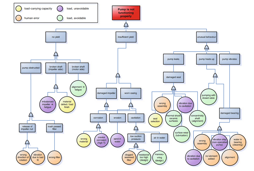
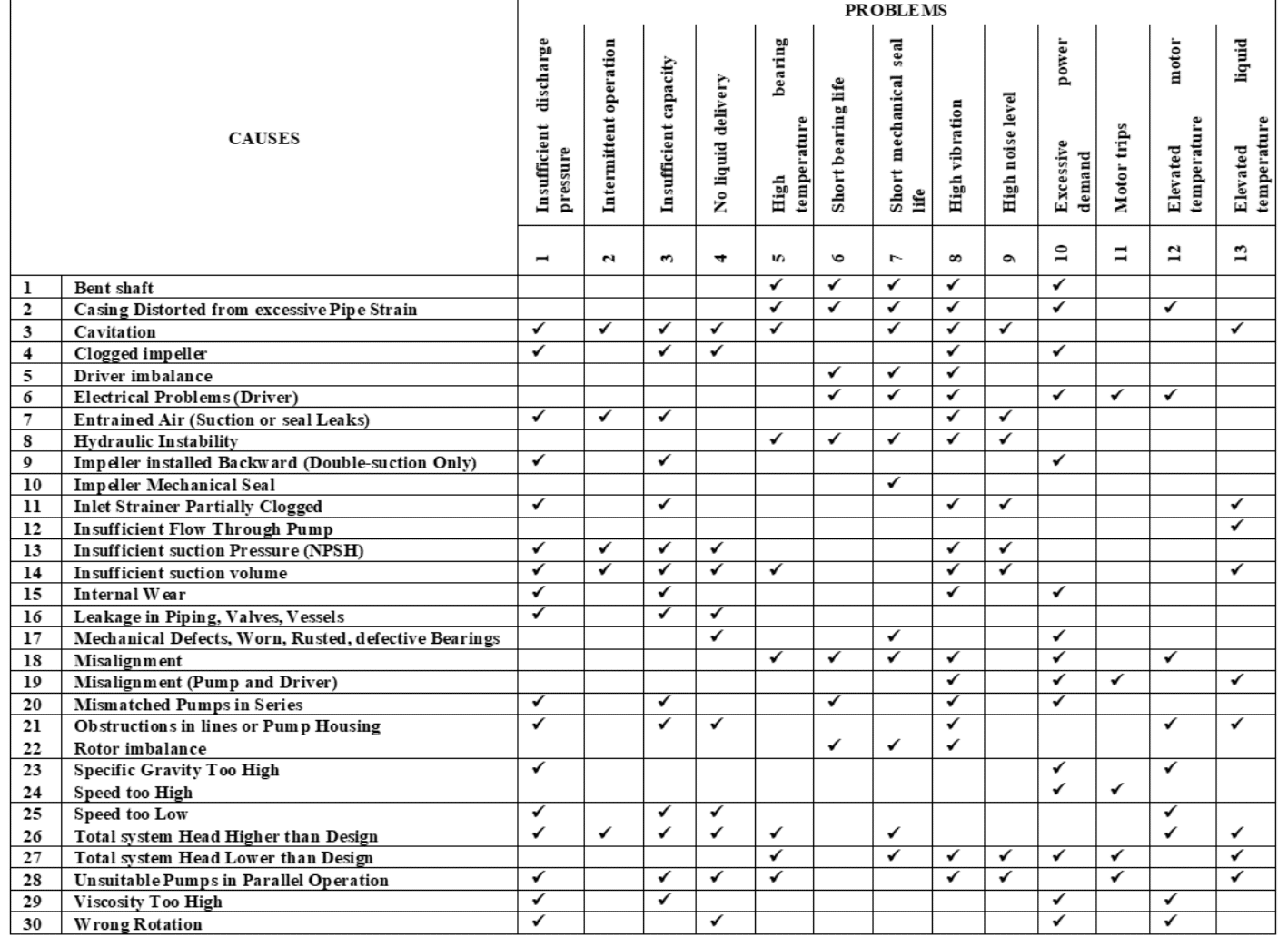
Table 3: Causes and problem chart of centrifugal pump
Failure Modes, and Effects Analysis
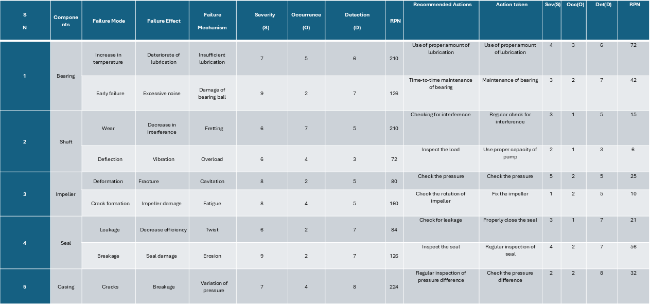
Failure Modes and Effects Analysis (FMEA) is a systematic approach for discovering, assessing, and avoiding possible reliability problems (how it could fail) in systems, products, and processes early in the development cycle, when it is simpler to take corrective steps, therefore improving reliability through design. The goal of FMEA is to prevent issues, improve safety, and increase customer contentment. The Risk Priority Number (RPN) ranks the relative importance of each failure mode and its consequences. The dependability of components is examined using mathematical modeling and numerical simulation based on RPN.
RPN is a numerical risk assessment issued to a process or stages in a process as part of Failure Modes and Effects Analysis (FMEA), in which a team provides quantitative values to each failure mode that quantify the likelihood of occurrence, the likelihood of discovery, and severity of the effect.
Table 4: FMEA chart of centrifugal pump
Recommended actions and knowledge
It is important to have knowledge on corrosion, erosion, and cavitation to ensure trouble trouble-free operation of a centrifugal pump. These factors are responsible for the damage and failure of the system.
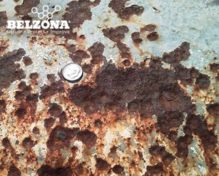
Corrosion and its prevention
Corrosion is when a refined metal is naturally converted to a more stable form such as its oxide, hydroxide, or sulfide state which leads to deterioration of the material. Metal corrodes when metal interacts with another material, such as oxygen, hydrogen, an electrical current, or even dirt and germs. Corrosion can also occur when metals such as steel are subjected to excessive tension, causing the substance to split.
There are various kinds of corrosion that occur to the metal during various periods of its lifecycle when subjected to different environmental conditions. They are discussed below:
Uniform corrosion
Uniform corrosion is the most prevalent type, generally occurring uniformly across broad regions of a material’s surface.
Pitting Corrosion
Pitting, one of the most aggressive kinds of corrosion, may be challenging to forecast, detect, and characterize. This type of corrosion occurs when a local anodic or cathodic point forms a corrosion cell with the surrounding surface. This Pitt can form a hole or hollow that usually penetrates the material vertically down from the surface.
Crevice Corrosion
This corrosion happens when oxygen is scarce, such as behind washers or bolt heads. Localized corrosion is often caused by a variation in ion concentration between two metal sections. The stationary microenvironment restricts oxygen circulation, which halts re-passivation and causes the pH balance to shift away from neutral.
The disparity between the crevice and the remainder of the material adds to the elevated corrosion rates. Crevice corrosion can occur at lower temperatures than pitting corrosion, although it can be reduced by correct joint design.
Intergranular Corrosion
Intergranular corrosion occurs when impurities are present at the grain boundaries that develop during the solidification of an alloy. The enrichment or depletion of an alloying element at the grain boundaries can also induce it. This form of corrosion happens along or close to the grains, damaging the mechanical characteristics of the metal even though most of the material is intact.
Stress Corrosion Cracking
Corrosion caused by stress Cracking is the formation of cracks resulting from a corrosive environment, which can lead to the failure of ductile metals when subjected to tensile stress, particularly at high temperatures. This form of corrosion is more prevalent in alloys than in pure metals. It depends on the unique chemical environment, with relatively modest concentrations of active chemicals necessary for catastrophic cracking.
Galvanic Corrosion
When two different metals with physical or electrical contact are submerged in a shared electrolyte (such as salt water) or when a metal is subjected to varying amounts of electrolyte, this type of corrosion occurs. When two metals are submerged, the more active metal (the anode) corrodes faster than, the more noble metal (the cathode). When utilizing a sacrificial anode to protect a building from corrosion, the galvanic series identifies which metals corrode more quickly.
Prevention of corrosion
The effective ways to control corrosion are given below:
- Use drying agents
- Use a coating or barrier product such as grease, oil, paint, or carbon fiber coating
- Lay a layer of backfill, for example, limestone, with underground piping
- Use a sacrificial anode to provide a cathodic protection system
- Make sure the metal surface stays clean and dry
- Use non-corrosive metals, such as stainless steel or aluminum
Erosion
Erosion is the gradual, layer-by-layer destruction of the surface of the metallic materials by mechanical action or electrical discharges. The erosion of the metals occurs upon the frictional rubbing of surfaces, wear, and cavitation, as well as upon the action of strong gas or liquid currents upon a surface, especially at high temperatures.
Factors affecting the erosion of centrifugal pump
- Fluid containing salt and silt
- High tip velocity may cause erosion in the impeller
- Turbulence which sometimes causes uneven wear
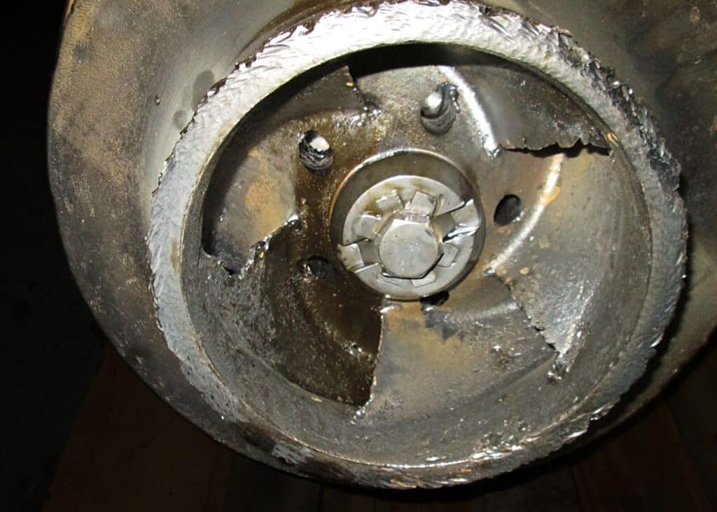
Cavitation
Cavitation in pumps refers to the rapid formation and collapse of air bubbles in a fluid. Bubbles may not appear particularly forceful, but the bubbles produced in pumping systems are nothing like the ones produced by waving a wand around with small children. Tiny bubbles formed by pressure variations inside pumps rupture and create shock waves that repeatedly recur, eroding the components. In many circumstances, the cavitation force is strong enough to pit metal pump components such as the impeller and destroy pump seals.
Some ways to prevent cavitation are:
- Selection of the right pump
- Avoid pockets where air or vapors can accumulate
- Routine maintenance
- Proper installation
SAFETY
Because centrifugal pumps are one of the most often utilized pump systems in the home and industrial settings due to their adaptability in many applications, there is an elevated risk of workplace accidents. As a result, it is critical to understand the best centrifugal pump safety recommendations to remember before, during, and after the pump operation. Some of the safety protocols that we must follow while using a centrifugal pump are:
Read and follow the operation manual
Before installing the pump, the proper instruction manual must be read. Before conducting maintenance or operation, the recommended specifications of components must be verified.
Avoid overheating
Centrifugal pumps have the potential to overheat and destroy internal components. Furthermore, they might cause catastrophic burns to anyone maintaining the pump. Allowing a Centrifugal Pump to overheat is dangerous. During operation, keep the suction and discharge lines open.
If the pump overheats, turn it off and let it cool. Allow the drain cap to vent before resuming pump operation. Always wait until the pump has cooled before touching it. Simply removing the cover plate might result in severe damage.
Replace old parts
Worn-out Centrifugal Pump components frequently cause workplace accidents and can even harm the pump itself. If a minor item, such as a bearing or casing wear ring, gets worn out, it might produce catastrophic safety hazards.
If the pump shaft begins to wobble, the pump may overheat. To avoid this problem, inspect the safety suction lines and pipe plugs regularly. Sealants eventually wear away, allowing foreign items inside the pump itself. Replace worn-out parts and components as frequently as feasible.
Test for air leaks
Air leaks become typical as components wear out and age. The pump typically makes a loud, gravel-like noise when air is present. First, ensure that the noise is not caused by cavitation. Examine the suction gauge reading. If the readings are unpredictable, it is possible that the suction flap valve, seals, or hose are worn out and must be replaced.
Understand Suction blockages
Centrifugal pumps can become clogged with extraneous items or mismatched components. When the rubber liner of a suction hose comes away from the fabric, blockages can form. However, the actual problem might be a combination of difficulties.
Checking for these obstructions necessitates understanding what is being pumped and the pump’s architecture. Avoid difficulties by maintaining suction lines short and straight, which will aid in the elimination of vapor pockets or bubbles. Also, check sure suction strainers are not blocked or unclean to avoid cavitation.
Perform routine shut-off tests
This Centrifugal Pump test will assist in determining the internal wear of the pump as well as the vacuum pull: Start the pump to maximum flow, then gradually close the discharge valve. Take note of the discharge and suction gauge readings.
The measurement should equal the pump’s maximum performance pressure at zero flow. This condition guarantees that the pump can work as intended.
Proper installation
Professional installation is required for all pumps, especially centrifugal pumps. Failure to properly install these pumps can result in serious safety violations and penalties.
To guarantee the safety of others, use a professional to install these pumps professionally. While it may be tempting to have staff install a new pump themselves, doing so may result in additional costs and fines.
Achieve proper alignment
Ensure the driver’s alignment is correct to ensure the lifespan of a centrifugal pump. It is not just a safety problem but may also help save money that would otherwise be spent on repairs. If the pump’s bearings and driver are not correctly aligned, they will wear down and may cause the pump to overheat.
If left unnoticed, couplings will eventually fail. Make sure to check the driver’s alignment at least once a month. Inspect more regularly if jobs are done in a higher capacity or more frequently.
CONCLUSION
A centrifugal pump is a mechanical device used to move fluid by the rotational motion of the impeller. They are subjected to operating in different environmental conditions, and sometimes the life of materials like lubricant is expired. Due to these, the pump may get reduced in efficiency, or parts get damaged, which ultimately increases machine downtime and the need to spend unnecessary money on maintenance. So, this case study explains how the procedures described in various sections can be applied to a real-world situation. They also show how studying the failure mechanism and accompanying stresses may assist fix such problems in a reasonably simple way.
Centrifugal pump failure must be anticipated to decrease the machine’s downtime. We can create a plan using RM, PM, PdM, CBM, RCM, RBM, TPM, and software-based maintenance. It can help us to minimize failure in the future and help to reduce the maintenance cost. Similarly, we can use fault tree analysis and an FMEA chart to anticipate problems that can be caused in the centrifugal pump, arrange problems according to vulnerability, and perform the maintenance task accordingly to get the machine’s smooth operation and use it for longevity.
Do follow Mechinsights for more mechanical engineering-related content.
4 Comments
Pingback: Cyber-Physical Systems: Bridging Big Gap Between Digital And Physical Worlds - MechInsights
Pingback: 3D Printing Technology: Major Breakthrough
Pingback: Mechanical Systems: 4 Steps for Optimization of Energy Efficiency | MechInsights
Pingback: AI Automation and Humanoid Robot's Advantages: Transforming